SuperNEMO
The success of NEMO-3 motivated an effort to construct a
new and better detector called SuperNEMO. It is designed to have larger
amounts of double beta decay sources and to be made out of materials
which are less radioactive than the ones used to build NEMO-3, further
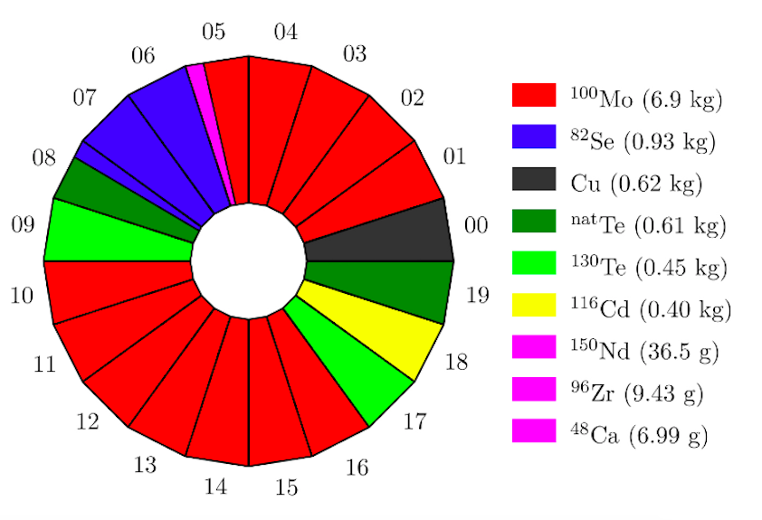
reducing the possible background. SuperNEMO will also be composed of 20
modules. Approximately 5-7 kg of double beta decay isotopes will be
installed in each module, allowing it to have at least 10 times more
source mass than its predecessor. The materials to build the modules
were chosen so that, once built, each module will be less radioactive
than 8 bananas.
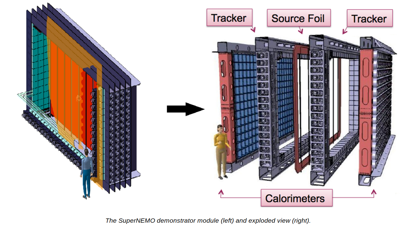
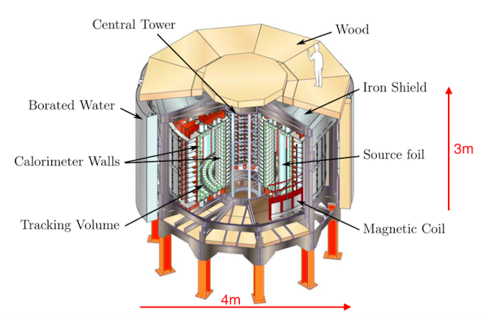
In contrast to the cylindrical shape of the NEMO-3
detector, the SuperNEMO modules exhibit a rectangular geometry. This
allows for a staged approach to the construction of the detector,
meaning that a module can be taking data while the rest of the modules
are being built. It also makes it possible to build this kind of modules
in other underground locations if desired. Lastly, this geometry
facilitates the extrapolation of sensitivity and performance from a
single module to the whole SuperNEMO detector.
The first module, called the demonstrator, is currently under construction. It will be populated with 82Se
as its only source of double beta decays. However, since virtually any
double beta decay source may be used, the possibility of enriching and
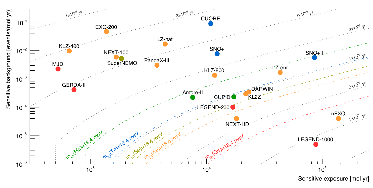
using 150Nd and 48Ca is being investigated. The SuperNEMO experiment is aiming to reach a sensitivity greater than 1026 years for the half life of neutrinoless double beta decay, which translates to an effective neutrino mass of 50-100 meV.
Our group’s involvement with this experiment consists of
two calibration systems: The Calibration Source Deployment System, and
the Light Injection System. Information about each of them can be found
in the following links:
Radioactive Source Deployment System
The radioactive source deployment system consists of six
oxygen-free copper plumb bobs suspended from stainless steel wires
inside the SuperNEMO source frame. Each wire is wrapped around a wheel
on top of the detector (housed inside a stainless steel vessel) which
may be rotated by a stepper motor, lowering and raising each plumb bob.
At seven fixed positions on each wire above the plumb bobs, 207Bi
calibration sources are attached, making it possible to introduce the
sources into the detector. At the bottom of the source frame there are
six nests with laser light passing through them. Each plumb bob has a
hole big enough for the laser beam to pass through. As a plumb bob
enters a nest, it first interrupts the laser; this interruption is
detected by a computer which slows down the motor. As the plumb bob
continues descending, it reaches a position where its hole aligns with
the laser beam. The computer is once again alerted by this change, and
it stops the motor completely.
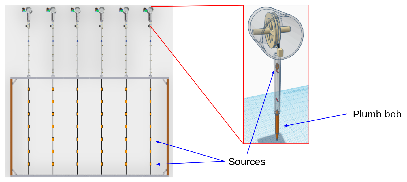
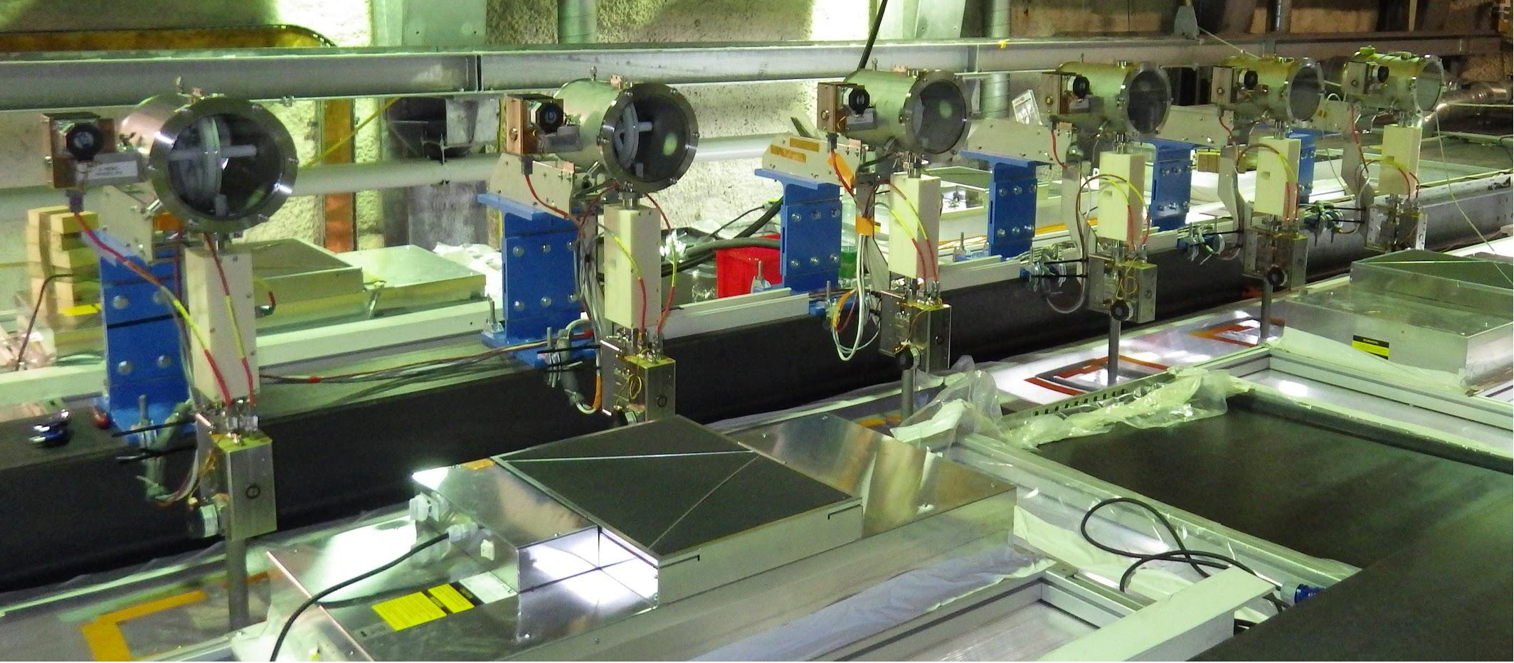
Left: The six different calibration lines installed on top of the
SuperNEMO source frame. Right: A close up of one of the vessels which
houses the wheels which raise and lower the plumb bobs and calibration
sources.
The system is fully automated. Photodiode amplifiers are used
to create electrical signals whenever they receive light from the
lasers. These signals are the way the computer knows when the lasers are
interrupted and uninterrupted. The computer which controls the whole
system, called CompactRIO, communicates with the stepper motor drivers
which actuate the stepper motors that deploy the plumb bobs. The
CompactRIO has 64 inputs/outputs, and it uses LabVIEW as the language
that interprets and analyzes the inputs to decide which outputs need
to be sent.
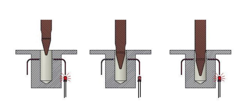
Computer drawings showing how a plumb bob interacts with the light
passing through a bottom nest in order to find its lowest position.
The radioactive source deployment system has already been installed and
incorporated into the SuperNEMO detector. The mechanics of it
(introduction and retrieval of the calibration sources) have already
been successfully tested, and it will begin performing calibration runs
some time in the year 2021.
Vessels mounted on top of the SuperNEMO detector.
Light Injection and Monitoring System
The
Light Injection and Monitoring (LIM) System injects pulsed UV light
into each optical module of the SuperNEMO calorimeter via optical fibers
to control and monitor their energy response over time. The aim of the
LIM system is to guarantee the stability of the calorimetric response to
within 1%. The LIM system consists of 20 UV-LEDs illuminating ~1500
optical fibers routed to optical modules. Each LED illuminates a bundle
of ~75 fibers. Reference optical modules outside the detector are used
to monitor the energy of 207 Bi sources as well as the light levels of
some optical fibers connected to each of the 20 UV-LEDs. By comparing
the light from the UV-LEDs to the constant energy
By
comparing the light from the UV-LEDs to the constant energy of the 207
Bi sources, it is possible to correct any fluctuations on the UV-LEDs.
After making those corrections, that light can be used to see if the
energy response of the SuperNEMO optical modules is drifting over time.
Tests with a top-bench version of this system at UT Austin outperformed
the 1% stability goal. The system has been installed and run
successfully at the site of the SuperNEMO detector. It will also begin
performing calibration runs some time in the year 2021.
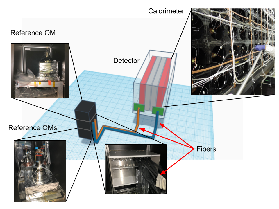
Schematic of the Light Injection and Monitoring System together with actual photos of the system as it is currently installed.